La rivista e il marketplace globale per gli appassionati di auto d’epoca, creati da appassionati.
La rivista e il marketplace globale per gli appassionati di auto d’epoca, creati da appassionati.


Filter
Faccia la sua scelta
- Automobile
-
Marca >>
-
Anno >>
-
- Motociclette
-
Ubicazione >>
- Parti e altro
-
Marca dell'auto >>
-
Produttore >>
-
Categoria >>
- Biciclette
-
Anno >>
-
Paesi



The French Gandon - probably the world's first all-wheel-drive Lorry



What was the first all-wheel-drive Lorry? Some people might answer - the American FWD. But according to automobile historian Vasily Shishka, the first all-wheel-drive Lorry was the French Gandon steam lorry made by Julien Gandon. Today Vasily tells us more about Julien's invention.
The French Gandon
"Julien Gandon from Paris demonstrated his vehicle for the first time at the World Exhibition in Paris in 1900. It had previously been advertised that this lorry was to participate in the French truck and omnibus competition the “Poids Lourds” in 1897, but for some reason, this did not happen. The maker - Julien Gandon - applied for a patent “Improvements in apparatus by which mechanical propelling: power can be applied to the four wheels of a road vehicle” on 6th June 1896.
Unfortunately, we still have only one image of this vehicle which comes from the magazine "Horseless age" (08-08-1900). Other magazines for some reason either did not see this interesting truck at the exhibition or did not appreciate the importance of the concept. The photo shows the heavy steam wagon with iron tires, in which all four wheels are driven. Engine and boiler are placed in the front, near the driving position.
The boiler is of the vertical water tube type and has a heating surface of 10.2 square meters (110 square feet). Liquid fuel was used, and the regulation of the burners was automatic. The pressure set was 13.6 atmospheres (200 psi), and a triple-expansion engine was used to obtain economical operation. A condenser was also used in connection with the engine (listed as 12 HP) and the amount of water required to be carried was therefore small. With a total weight of 2.5 tons, the vehicle could carry a load of 3 tons, besides towing a trailer carrying 2 tons. The consumption of kerosene when the vehicle was fully loaded was between 3.8 and 5 litres per hour with a speed of 3-12 km per hour.
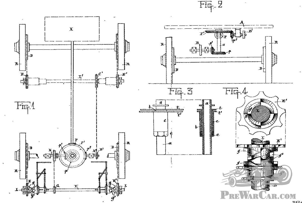
The transmission of this vehicle has six chains and four clutches, two on each axis. Each clutch (Figure 4) can transmit rotation in one or the other direction. Accordingly, using these clutches, it is possible to transmit torque to the front or rear axle individually or both together."
The patent
To learn more about the transmission device, a quote from the patent:
This invention has for its object improved apparatus by which a uniform, distribution of the load upon the floor of a carriage or other vehicle can be affected. The improved apparatus consists essentially (as shown in the accompanying drawing) of a vertical central pin b (on which the fore-carriage turns), of iron or steel and having a central opening from end to end so as to allow the passage through it of a hollow spindle a through which pass rod's or bars actuating the brake and disengaging clutches; and of an external fixed socket c through which the hollow pin last-mentioned passes.
This improved method of making the turning pin hollow allows traction to be applied to all four wheels whilst the brake can be applied to those in front without interfering with the movement of the carriage in any direction.
The improved arrangement of apparatus consists of four beveled toothed gears P, P1, p, p1, (Figures 1 and 2) arranged under the floor A of the carriage (as shown in Figure 1) and of shafts L and Ll, one L arranged in front and carried under the front carriage, and the other L1 arranged at the back, two engaging and disengaging clutches (Figure 4) being arranged on each of these shafts. Also, of an arrangement of apparatus (Figure 3) consisting of a shaft a, a hollow pin b, and a socket c, arranged and combined as shown in the figure. Under the floor, A of the carriage is arranged horizontally one of the four beveled toothed wheels P1 which is keyed to the upper part of the spindle an already described. It is driven by a corresponding toothed pinion P actuated by a suitable motor, and the spindle carries a similar beveled toothed wheel p at its lower end, which itself drives a beveled toothed pinion p1 on a short transverse shaft.
The central spindle a is hollow in order to allow the passage of rods or bars actuating the brake and the clutches q, q1 already described.
The spindle a can turn freely in the outer hollow central pin b in which it fits, which is itself firmly fixed by the bar t to the frame of the carriage, whilst the outer socket c through which this hollow pin b passes, is itself fixed to the bar of the fore-carriage by a bar A nut eat its lower end prevents the hollow pin b from rising out of the exterior socket c. Upon the axis K which carries the beveled toothed pinion p, last described (as shown in Figure 1, which is a plan of the mechanism) is fixed a chain wheel B driving by an endless chain a similar chain wheel G fixed upon the transverse- shaft L carrying the clutches already described. At the ends of this shaft, L are fixed two toothed wheels E and E1 having on their faces two sets of concentric: angular teeth engaging with the clutches. Figure 4 shows these sets of angular teeth upon a larger scale.
The two toothed wheels E, and E1, last described run loose upon the transverse shaft L, to which, however, either of them can be coupled as desired by means of one of the clutches q and q1 in an ordinary way. One part of each clutch q1 revolves, with the shaft L, but can move endways along the latter for a certain, distance upon the key. Upon the clutches, q1 have fitted the clutches g which can move endways upon the former in the same way as those q1 moves upon L.
A similar transverse shaft L1, fitted and actuated in the same way is arranged to operate the back wheels of the carriage.
As shown in Figure 4, each clutch consists of a part running loose upon the shaft L, this part consisting of a chain wheel and two, concentric sets of angular teeth pointing in opposite directions, that is to say, the outer set is used for travelling forward and the inner set for travelling backwards, according to as the shaft L is driven in one or other direction by the motor. These two sets of teeth and the chain wheel carried by them are driven by two similar sets, the outer one of which slides upon the inner one, and the inner one upon the shaft L, both sets being always driven by the shaft which carries them.
If now, by any convenient arrangement of levers or the like, the clutches on the chain wheels E and E1, are engaged or disengaged, the movement in the required direction is transmitted to the wheels of the carriage by means of endless chains passing round the chain wheels and also round corresponding chain wheels D firmly fixed to the spokes of the carriage wheels R, which are, therefore, set in a revolution.
In the arrangement illustrated in the drawing, the motor X which drives the whole of the mechanism is arranged below the floor at the back of the carriage, leaving the whole of the latter free for its load. If desired, however, it may be placed under the seat of the conductor or in any other desired position, the necessary alteration of the gear being made.
The two back wheels are driven by the pinion p2 which gears with P1 and drives by the shaft K1 the chain wheel B1, which transmits its movement, by a chain to the wheel C1 fixed upon the shaft L1, which is in every respect similar to L.
Do you have any additional information or photographs of the French Gandon steam lorry? Please comment below.
Words by Vasily Shishka.
This article was created with help in the preparation by Chris Wedgwood and Dan Soudey.
Pubblicato:
mercoledì aprile 29th, 2020
Facebook
LinkedIn
Twitter
WhatsApp
Email
Copy